Bottom Vision Exposure: Why It Is Set by Hand
Bottom vision is the one place in OpenPnP where a number you type decides whether a part gets aligned, and it is the first thing people change when a placement starts drifting. On a Vertex 4 the bottom camera ships focused and its position is already set, which leaves exposure as the piece of the vision chain the owner finishes. This page covers what that value controls, why OpenPnP wants it fixed instead of automatic, and a test that sorts a threshold fault from a calibration fault before you start turning dials.
What the exposure value controls
The exposure value decides the gray level the part occupies in the frame. Everything downstream compares that level against the background.
Each stage of the bottom vision pipeline does one job. ImageCapture grabs the frame, a MaskCircle stage blacks out everything outside the configured part diameter, a Gaussian blur suppresses detail smaller than the minimum detail size, and a MaskHSV stage keys the background out. The pipeline then measures the offset of what survives from the nozzle center and whether it is rotated.
Background calibration is what fits the mask. OpenPnP images the empty nozzle tip and the background, finds a brightness cutoff the background stays below, and writes the resulting HSV box into the MaskHSV stage. Anything the part contributes has to sit clearly above that cutoff. The calibration is fitted once against an empty tip and then left alone, and it encodes a single assumption: the part is brighter than the background. Exposure is what makes that assumption true for the tip you actually have mounted.
That is why the calibration is refreshed so often. It re-runs together with nozzle tip calibration, which OpenPnP renews at least whenever the machine is homed, and again after a tip change. Room light drifting over an afternoon is inside the design.
Why automatic exposure is the wrong tool here
OpenPnpCaptureCamera exposes Exposure, Brightness, Contrast, Gamma and White Balance as device properties, each with an Auto checkbox. The OpenPnP wiki is direct about those boxes: automatic settings produce unstable conditions for computer vision, because a threshold only means the same thing frame to frame if the levels feeding it stay put. It goes as far as suggesting a camera which cannot switch automatic exposure off should be replaced.
The failure mode is specific to bottom vision. Background calibration runs against a frame of an empty tip. The vision pass runs against a frame with a part on that tip, lit by its own reflection. Auto exposure is designed to make both frames look reasonable, which is exactly the change you want to prevent. The cutoff was fitted against one set of levels and the mask is applied to another.
The cost also shows up in timing. Auto exposure needs time to settle on a value, and camera settle time has to cover it. OpenPnP's simple settle method waits a fixed 250 ms by default, and that number grows when the camera is still adapting.

Two faults that reach you as one complaint
"Vision is misaligned" covers two different things, and they want opposite fixes. The split is whether the pipeline drew a mask over the part at all. Test Alignment with the camera preview open answers that in one click.
| What you see | What bottom vision returned | Where to look first |
|---|---|---|
| Every placement is off in the same direction | An offset, repeatable | Nozzle tip offset, runout, or fiducial position |
| The offset scatters placement to placement | Offsets with run-to-run spread | Exposure margin, settle time, or a stale background baseline |
| The part lands rotated, or shifted by roughly one pad pitch | An offset computed from part of the part | Clipping, threshold, or Max Part Diameter |
| No alignment, retry requested, or a pick tolerance error | Nothing | Exposure below the cutoff, or a genuinely bad pick |
The third row costs the most time, because nothing errors. Solder-plated pins and gold pads are what clip. Once a row of pins saturates at white, the gaps between pins are no longer darker than the pins themselves, so the mask reads the whole row as a single bright region and the measured center lands wherever that region's balance falls. Every placement inherits the error and the log looks clean.
The mirror case is too little exposure. The part's darker body drops below the cutoff, the mask covers only the bright pins, and the offset is computed from a subset of the part. Same complaint, same correction applied to the wrong center, opposite cause.
Max Part Diameter belongs on that list too. It is applied as a circular black mask, so a part larger than the configured diameter has a bite taken out of the picture before any threshold sees it. Minimum Detail Size works the other way and discards anything smaller than the smallest pad, pin or ball you told it about.
A ten placement test that separates the two
One successful alignment proves nothing. It says the part happened to land inside the margin, which is not the same as having a margin.
Pick the same part from the same feeder and align it ten times without changing anything else, logging the offset and rotation bottom vision returns each time. Ignore the individual values and read the spread.
Scatter that changes sign between attempts, with the part passing some runs and failing others, means you are sitting on the edge of a threshold. That points at exposure, lighting, or settle time.
A repeatable bias in one direction has two possible owners: fixed geometry, or a mask that always includes or excludes the same part of the part. Separate them by sweeping the exposure. Step it through a few values, keeping the mask drawn each time, and re-run the ten placements at each step. If the bias moves with exposure, the mask extent is the cause. If the bias holds still while the mask is still drawn, geometry is the cause, and the answer lives in tip calibration rather than in the camera settings.
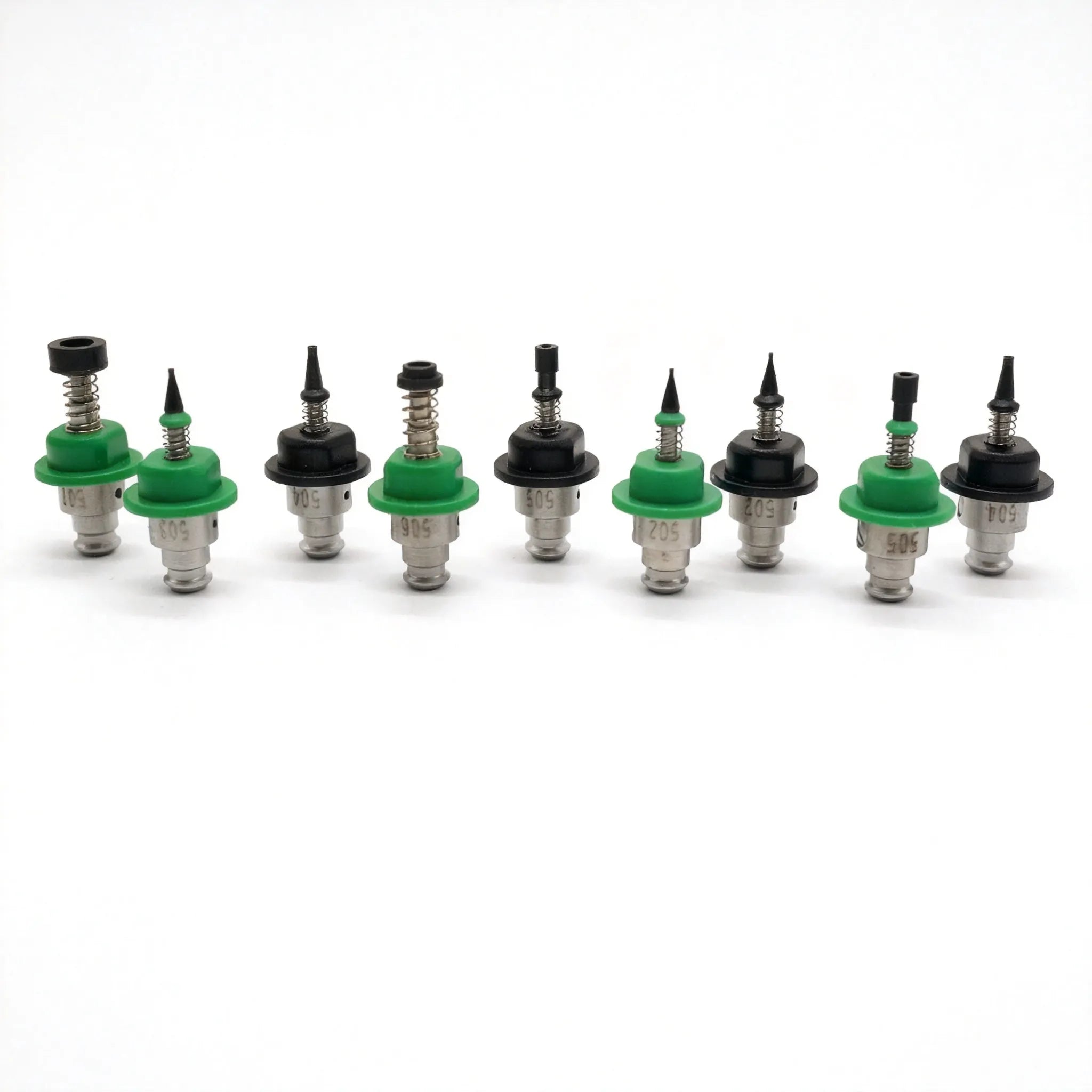
Re-run the whole thing after any tip change. On a Vertex 4, swapping a Juki-compatible tip invalidates the runout measurement and the tip's background baseline, so numbers taken before the swap describe a different tip than the one now on the head.
Setting the exposure once, in the right order
- Fix the light before the exposure. OpenPnP switches the camera light on before capture and before settling. A dim light forces an exposure high enough to drag the noise floor up with the signal, and cheap LEDs tint the frame, which matters the moment you key the background by color.
- On the Device Settings tab, switch off Auto on Exposure, Brightness, Contrast and Gamma, and return Contrast and Gamma to the default values shown to the right of each slider.
- Set Sharpness to its minimum. Artificial sharpening invents edges, and the pipeline believes them.
- Aim the camera at the brightest part or board you actually run, then raise exposure until only tiny pinprick highlights clip. Broad areas going to white means you passed the useful point. A correctly exposed frame can look slightly dark to you.
- Turn on Freeze Properties, which stores the values in machine.xml and reapplies them when the camera is reopened and when the machine homes. Without it, the device driver decides what to hand back.
- Set Threshold and Minimum Detail Size last, against a real part, using Test Alignment and the preview.
When to stop adjusting exposure
If the background and the part sit at the same brightness, no exposure value creates a gap between them. That is a lighting problem, and a diffuse light from the side usually helps more than any slider position.
Two stages sidestep the threshold. DetectCircularSymmetry and DetectRectlinearSymmetry find round and symmetric shapes without depending on color, brightness or contrast, and they tune themselves. Parts too large for the camera view, or too irregular to mask well, go to Vision Compositing, which takes several shots and combines them. Multi-shot alignment also removes most of the error a tipped nozzle produces through the wide-angle lens these machines use.
The order I check it in
Is a mask drawn over the part? If not, exposure and lighting come first. If it is, run the ten placement test before touching a slider, because a repeatable bias is never fixed by exposure alone. Clipping comes next, then tip calibration and the background baseline, and the pipeline parameters last, since they are the only settings in the chain where a wrong value still produces a plausible-looking frame.