Tombstoning Causes: What a Desktop Machine Can and Cannot Fix
Tombstoning shows up after the oven, which is why people go looking for the fault in the oven. By the time the board comes out, the decision was already made. A chip stands up when one of its two joints melts and pulls before the other one does, and everything that made one joint earlier than the other happened upstream of reflow.
A desktop placer gets blamed for that more often than it deserves. It also gets a free pass on a few things it does control. This page sorts the causes by which hand owns them and gives the machine-side ones a number you can check on your own bench.
Why one end lifts
Murata's write-up on chip mounting calls the failure the tombstone, or Manhattan, phenomenon and describes it as an imbalance in the tension acting on the two electrodes while the solder is molten. One side lifts and the chip rotates up on it. Murata's own list of what feeds the imbalance is short: the land surface area on each side, the amount of solder, temperature, and the variance in mounting position.
A reflow profiling paper from Circuit Insight divides the forces into three: the weight of the chip, the surface tension underneath it, and the surface tension on its side. The last two are what rotate a 0402. Whichever paste brick melts first wins that argument.
The useful question is which of your two joints got hot or wet first, and which step in your process made that happen.

Paste volume is set at the printer, not the machine
Unequal paste is the first thing to rule out, and it is the easiest one to rule out, because you can see it before the head ever moves. An off-target print or a worn aperture puts more solder over one pad. More solder means more thermal mass under that joint, and that joint then melts later than the other.
The brick height is the stencil thickness. IPC-7525's conventional foil for mainstream work down to 0402 is 0.10 mm (4 mil), with an aperture area ratio at or above 0.66 for reliable release. A 0.7 by 0.35 mm aperture at 0.10 mm deposits 0.0245 mm³ of paste. That is small enough that a 30 µm smear across one pad changes the balance between the two joints in a way you can see under a microscope.
You cannot fix a smeared print with placement calibration. If the tombstones sit on one pad of one footprint and every other part on the board is fine, leave the placer alone and go look at the print.
Pad symmetry is set in the board file
A land that connects straight into a copper plane keeps drawing heat through the whole preheat, so the paste on it stays solid while the pad next to it has already wetted. The same thing happens when the two lands of a footprint are different sizes, because the paste brick volume follows the aperture and the aperture follows the land. Murata's guidance is to copy the manufacturer's recommended land dimensions and keep the layout symmetric about the part.
This cause is also the reason a tombstone sometimes looks random on the bench. Tombstones on the same reference designator every run point at the layout. Tombstones scattered across different parts and different pads point at the process.
Placement offset: how much is enough
IPC-7351 builds the outer dimension of a land pattern from three tolerances added together: the part's own profile tolerance at 0.2 mm per side, the land pattern's fabrication tolerance at 0.05 mm per side, and the placement accuracy, which the standard takes as 0.1 mm diameter of true position. Placement accuracy is the number the machine is expected to hold, and 0.1 mm is all of it.
Murata's note on mounting is that a slightly faulty position corrects itself through surface tension when the paste melts, and a position error past the tolerance does not. The chip gets pulled toward the solder on one land instead. They add that as components get smaller, mounting accuracy matters more. A 0402 body is 1.0 by 0.5 mm, so 0.1 mm is ten percent of its length and twenty percent of its width.
Rotation spends the same budget. The end of the part sits 0.5 mm from the nozzle center, so a rotation error of θ moves it sideways by 0.5 · sin θ. On a 0402 that works out to:
| Rotation error | End of the part moves |
|---|---|
| 2° | 0.017 mm |
| 5° | 0.044 mm |
| 10° | 0.087 mm |
| 11.5° | 0.100 mm |
An angle error on its own can use the whole placement allowance the land pattern was designed around, before any X/Y offset is added on top of it. That is worth remembering the next time you blame a lateral shift for a tombstone.
What the machine does with that number
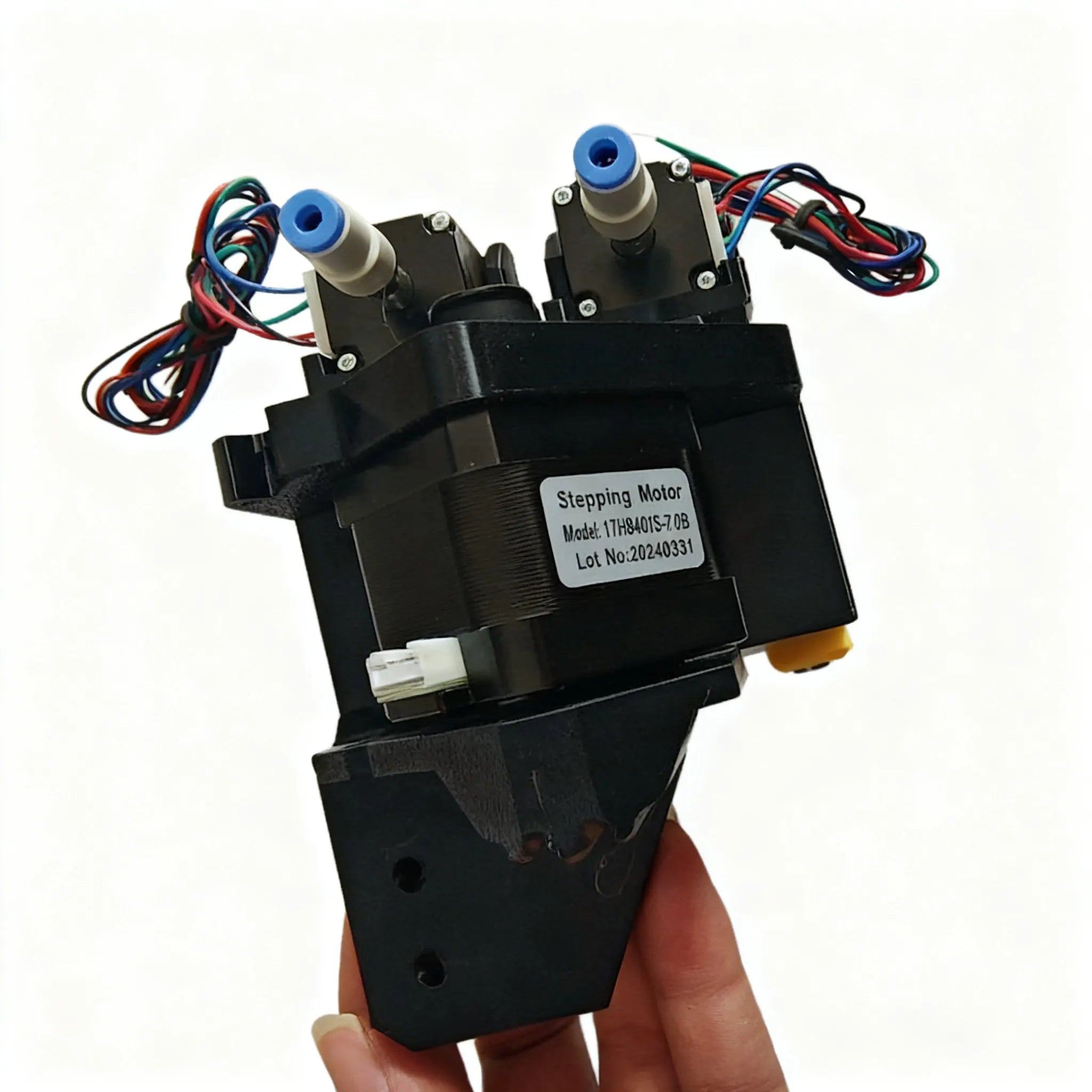
The Vertex 4 carries two Juki-compatible heads and its rated floor is 0402, which is exactly the size where this stops being theoretical. It has bottom vision, so after the pick the part gets imaged from below, its offset and rotation measured, and the correction applied before the nozzle comes down. The bottom camera position is set at the factory, and the two numbers an owner tunes are the exposure and the nozzle tip calibration.
The machine does not have a vacuum sensor, so a mis-pick is not caught by pressure. It is caught by the bottom camera, using the size and offset checks on the part alignment setup. A part sitting crooked on the tip, or one picked from a tape pocket at an angle, reaches the board at an angle unless vision sees it first.
Blow-off and release matter here too. The head is one of the few places in the process where a tombstone can be seeded by something other than paste or heat.
Placement height and the release
OpenPnP's place cycle is worth reading once if you own one of these machines, because the Z number is not a guess. The nozzle moves to the placement location plus the part height, so the tip stops one part-height above the board. The part hangs below the tip by its own height, which puts the bottom of the part exactly at the board surface.
That turns the part height setting into a direct control on how the part meets the paste. If the number stored for the part is 0.10 mm shorter than the real body, the part bottoms out 0.10 mm below board level. The paste beside it is one stencil thickness tall, so the joint is buried and the paste is pushed sideways. If the number is 0.10 mm too long, the part is released one paste thickness above the board and drops into the brick from a gap. Both are placement faults that look like a reflow fault on the finished board.
The release itself is a blow-off pulse followed by a place dwell. A blow-off level tuned for a 25 mm part is a lot of air on a 0402, and the chip leaves the tip onto wet paste. If your tombstones look scattered rather than aligned, check the part height, the blow-off level and the dwell before you change the oven.
Bottom vision only corrects what it can see
Bottom vision fixes offsets and rotation, up to the maximum pick tolerance, which also throws an error when a part is detected further from center than the tip was calibrated for. Past that limit you get a fault rather than a bad placement, which is the right behavior.
What it cannot fix is the calibration underneath it. Four things sit there, and each of them produces a different signature:
- Nozzle runout. Watch the tip in the bottom camera while you rotate the nozzle. If the center drifts off the crosshair, runout feeds a different offset into every placement angle. It affects the whole board rather than one part.
- Head offset. The camera-to-nozzle offset is only correct at the Z height where it was measured. Set it wrong and every placement on the board shifts the same direction and the same distance.
- Units per pixel. If the scale is off, bottom vision over- or under-corrects offsets, and the error grows with the size of the offset it is correcting.
- Pre-rotation. Rotating the part to its placement angle before the vision pass, instead of after, removes a step where the rotation can be lost. A larger part on a small tip rotates slower, which is one reason a heavy part lands off angle on a nozzle that handles 0402s fine.
The nozzle tip calibration procedure is the place to start, since runout and the tip-level offsets are measured there.
Reflow, after all of the above
The oven is the last hand and the one most often blamed first. The mechanism is still the same: one joint reaches liquidus before the other. Circuit Insight's fix for that is to cut the thermal gradient between the two pads before reflow, either by slowing the ramp from ambient to peak or by adding a short soak. Their recommended maximum ramp is 1.0 to 1.5 °C/s from ambient to peak, and a normal profile runs 0.5 to 2.0 °C/s. Intel's board assembly guide puts the rising ramp rate limit at 3 °C/s.
The classic tombstone profile is the one that runs a soak at 140 to 160 °C and then shoots straight up to peak. That fast rise through liquidus melts one end of a passive well before the other, which is the mechanism described in the same Circuit Insight paper. A brief dwell as the profile crosses liquidus lets both paste bricks melt together.
For SAC305 the liquidus sits at 217 °C, and the preheat soak band in the JEDEC-based profiles spreads from 150 to 200 °C for 60 to 120 seconds. Those numbers are a starting point, and your paste vendor's own profile envelope overrides them.
The check order I use
Work from cheapest to most expensive, and stop when the pattern matches.
- Read the pattern. Tombstones on one pad or one part every time: paste or layout. Tombstones scattered across different parts: placement or reflow.
- Look at the print. Paste height, and whether both bricks of the footprint are the same height and the same size. Compare the two against each other before you compare anything to a spec.
- Check the machine numbers. Part height, blow-off level, and place dwell for the part that tombstones. On a 0402, a 0.1 mm part height error is a whole paste thickness.
- Verify vision. Runout, head offset at board height, and units per pixel. Do this after any nozzle change.
- Change the profile last, and change one thing at a time. A slower ramp to liquidus plus a short soak costs a few seconds per board and fixes the case where the first four checks came back clean.
None of this needs a five-figure machine to act on. A Vertex 4 at $1,499 with a feeder set that indexes cleanly, Juki-compatible nozzle tips in the right size for the part, and a calibrated bottom camera will place 0402s all day. What it will not do is save you from a smeared print or a land pattern that heats one side of the part faster than the other.